Parallax Mapping
June 6th, 2025
Unreleased Project
Motivation
Imagine that you are working on a game with many tileable materials. For example, let's say you have set up a PBR material to represent a brick wall that uses different textures such as albedo, normals, roughness, etc. Now you are asked to give depth to every brick because it looks too flat even with a normal map. You wouldn't want to manually model every brick in the game, would you?
This is the perfect scenario to apply Parallax Mapping: An effect that simulates surface displacement per pixel using the view angle and a height map. This solution is faster and scalable, as the height map is created once and used on every brick wall already in existence and future ones as well.
Implementation
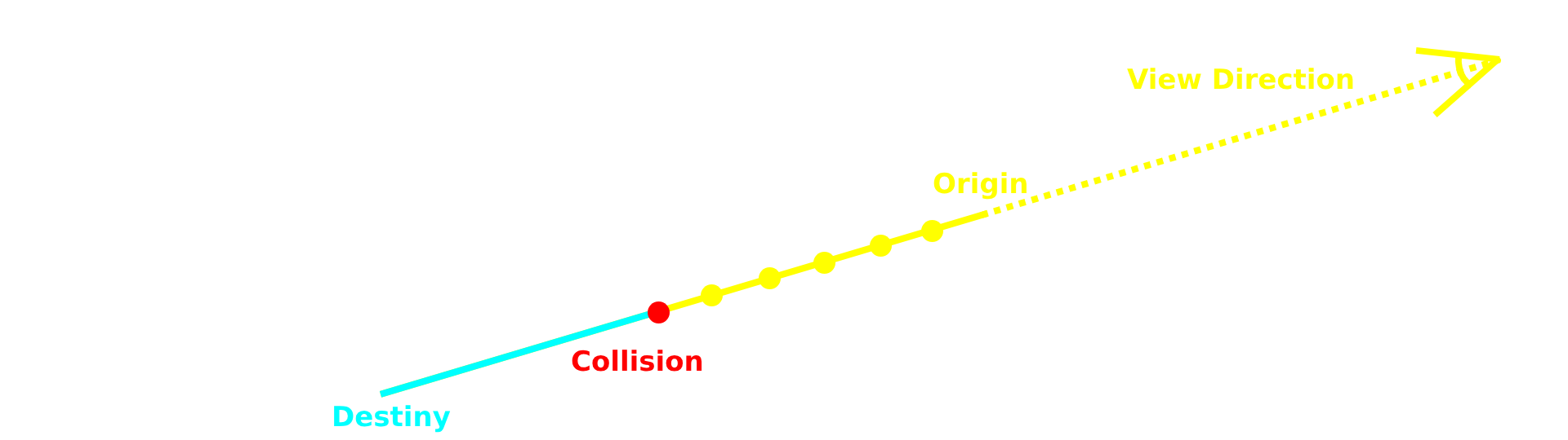
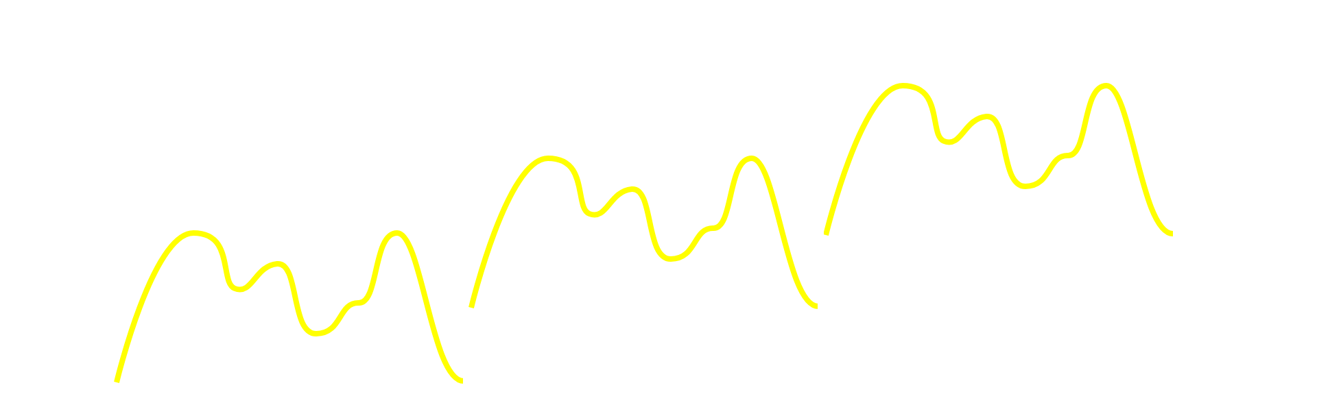
In order to simulate displacement for any given pixel, we'll need to raymarch thorugh the height map until a collision is determined. Once a hit point is detected, we will interpolate between the previous raymarch step and the current one to approximate the true ray collision point. The result will be a displaced UV that we can use to sample the rest of the textures later on.
That said, I must warn you that this effect is just a visual trick that is very good at faking depth. It has important limitations though, and some performance concerns may arise as well:
- Several samples of the height map are required and trying to represent highly displaced surfaces with accuracy might become expensive. On top of that, if the height map has high frequency details, using a low amount of samples will lead to flickering while moving the camera around.
- While raymarching the height field we'll be assuming a planar representation for every pixel given its position and normal. If the surface is not a perfect plane, the higher the displacement the higher the error we are going to get. In practice, we can usually get away with this error as it doesn't present obvious discontinuities from pixel to pixel.
- Since the effect works on a per pixel level, it can't simulate highly detailed silhouettes. Even on flat geometry, you will see that the effect seems to extend beyond the edges, almost as if you were looking through a portal. This is the side effect of not using real geometry, but you can mitigate these artifacts by using a low displacement scale and placing geometry in strategic ways.
For these reasons, I consider parallax mapping to be a good solution only for thin surfaces, and that's what I'll focus on in this article. At this point, you may be thinking that I dislike Parallax Mapping, but I actually think it is a powerful tool if used appropiately.
From World Space to Texture Space
The first step is to go from world space pixel coordinates to texture space. For this, we need to create a rotation matrix that lets us go from world space to tangent space. Then, we will use a texture scaling factor to go to texture space. For all of this, we need certain information available for each pixel:
- Normal (float3): The geometric normal of the surface, not the normal mapped one.
- Tangent (float4): The geometric tangent of the surface, including the fourth sign component.
- Texture Scale (float3): A texture scaling factor that tells us how much texture space is covered by the current triangle. This is a combination of UV scale and the tiling factor of the texture configured in the material. The third component is just the displacement strength configured for the material.
Using these parameters, the rotation matrix known as TBN can be constructed, and that is all we need to transform our coordinates.
        // TANGENT AND TEXTURE SPACE
        float3x3 GetTBN(float3 normal, float4 tangent)
        {
            float3 bitangent = cross(normal, tangent.xyz) * tangent.w;
            float3x3 tbn = float3x3(tangent.xyz, bitangent, normal);
            return tbn;
        }

        float3 ToTangentSpace(float3 v, float3x3 tbn)
        {
            return mul(tbn, v);
        }

        float3 FromTangentSpace(float3 v, float3x3 tbn)
        {
            return mul(transpose(tbn), v);
        }

        float3 ToTextureSpace(float3 v, float3 textureScale)
        {
            return v / textureScale;
        }

        float3 FromTextureSpace(float3 v, float3 textureScale)
        {
            return v * textureScale;
        }
Calculating the Texture Scale factor
Parallax mapping will be calculated in texture space because that means that a displacement of x units is always as "deep" independently of texture tiling. Later on, this consistency will allow us to calculate the displaced world position and depth offset of the surface, which is required to simulate self occlusion using shadow maps.
In simple words, the texture scale factor is: How much texture space does a triangle cover? A quad will have a triangle scale of (1,1), because a triangle's vertices bounds extend one unit horizontally and one unit vertically. I tried calculating this in realtime using screen space derivatives, but it breaks when the scale is not equal in both axes. I also tried using a geometry shader to have the complete triangle information. That kind of worked, but it presented discontinuities and the performance penalty was just not worth it. In the end, I used a custom importer script to calculate this factor in editor time and store the results as vertex attributes. Since a vertex may belong to different triangles, the final vertex scaling factor is an average of its surrounding triangles, this solves discontinuities but will lead to artifacts if UV stretching is highly irregular, so UVs must be carefully authored.
float3 textureScale = float3(rcp(scaleFactor * textureTiling), maxHeight);
The mesh importer uses a compute shader to precalculate the texture scale factor for each vertex. It takes into account vertex positions in tangent space and UVs to determine the scale factor for each triangle and averages the scales for each vertex:
        // EDITOR ONLY
        // This code runs in a compute shader when a mesh is imported

        float2 CalculateTriangleTiling(
            float2 uv0, float2 uv1, float2 uv2,
            float3 p0, float3 p1, float3 p2,
            float3x3 tbn)
        {

            float2 t0 = mul(tbn, p0).xy;
            float2 t1 = mul(tbn, p1).xy;
            float2 t2 = mul(tbn, p2).xy;

            float uv_min_x;
            float uv_max_x;
            float pos_min_x;
            float pos_max_x;

            if (t0.x > t1.x && t0.x > t2.x) //t0 is right
            {
                uv_max_x = uv0.x;
                uv_min_x = t1.x < t2.x ? uv1.x : uv2.x;
                pos_max_x = t0.x;
                pos_min_x = t1.x < t2.x ? t1.x : t2.x;

            }
            else if (t1.x > t2.x) //t1 is right
            {
                uv_max_x = uv1.x;
                uv_min_x = t0.x < t2.x ? uv0.x : uv2.x;
                pos_max_x = t1.x;
                pos_min_x = t0.x < t2.x ? t0.x : t2.x;
            }
            else //t2 is right
            {
                uv_max_x = uv2.x;
                uv_min_x = t0.x < t1.x ? uv0.x : uv1.x;
                pos_max_x = t2.x;
                pos_min_x = t0.x < t1.x ? t0.x : t1.x;
            }

            float uv_diff_x = uv_max_x - uv_min_x;
            float pos_diff_x = pos_max_x - pos_min_x;

            float uv_min_y;
            float uv_max_y;
            float pos_min_y;
            float pos_max_y;

            if (t0.y > t1.y && t0.y > t2.y) //t0 is up
            {
                uv_max_y = uv0.y;
                uv_min_y = t1.y < t2.y ? uv1.y : uv2.y;
                pos_max_y = t0.y;
                pos_min_y = t1.y < t2.y ? t1.y : t2.y;

            }
            else if (t1.y > t2.y) //t1 is up
            {
                uv_max_y = uv1.y;
                uv_min_y = t0.y < t2.y ? uv0.y : uv2.y;
                pos_max_y = t1.y;
                pos_min_y = t0.y < t2.y ? t0.y : t2.y;
            }
            else //t2 is up
            {
                uv_max_y = uv2.y;
                uv_min_y = t0.y < t1.y ? uv0.y : uv1.y;
                pos_max_y = t2.y;
                pos_min_y = t0.y < t1.y ? t0.y : t1.y;
            }
            float uv_diff_y = uv_max_y - uv_min_y;
            float pos_diff_y = pos_max_y - pos_min_y;

            float2 tiling = float2(uv_diff_x, uv_diff_y) / float2(pos_diff_x, pos_diff_y);

            return tiling;
        }

        float2 CalculateAvgWorldTiling(uint i) // i = vertex index
        {
            float3x3 tbn = GetTBN(i);
            float2 avgTiling = float2(0, 0);
            int triangleCount = 0;

            [loop]
            for (uint j = 0; j < _TriangleCount; j += 3)
            {
                uint a = _Triangles[j + 0];
                uint b = _Triangles[j + 1];
                uint c = _Triangles[j + 2];

                if (i == a || i == b || i == c)
                {
                    // AVG TILING
                    float2 uv0 = _Texcoord0[a];
                    float2 uv1 = _Texcoord0[b];
                    float2 uv2 = _Texcoord0[c];

                    float3 p0 = _Vertices[a];
                    float3 p1 = _Vertices[b];
                    float3 p2 = _Vertices[c];

                    float2 tiling = CalculateTriangleTiling(uv0, uv1, uv2, p0, p1, p2, tbn);
                    avgTiling += tiling;
                    triangleCount++;
                }
            }

            // AVG TILING
            if (triangleCount > 0)
            {
                avgTiling /= triangleCount;
            }

            return avgTiling;
        }
Defining the ray's origin and destiny
In order to raymarch the height map, we must determine where to start and where to end. We can use the transform functions to easily obtain a starting point. But in order to calculate the destiny, we need to know how far we'd have to traverse in the view direction to reach the maximum displacement, which is -1 in texture space. We can know that by inverting the z component of the view direciton in texture space:
        float FindTMax(float3 viewDirTS)
        {
            //float tMax = IntersectLinePlane(float3(0.0, 0.0, 0.0), viewDirTS, float3(0, 0, -1), float3(0, 0, 1));
            float tMax = -rcp(viewDirTS.z); //Simplified intersection of line to plane
            return tMax;
        }
Now, we can calculate the ray origin, direction and displacement for each raymarch step:
        // WS: World Space
        // OS: Object-Tangent Space
        // TS: Texture Space
        float3 viewDirWS = GetViewDirection(positionWS, true);
        float3 viewDirOS = ToTangentSpace(viewDirWS, tbn);
        float3 viewDirTS = ToTextureSpace(viewDirOS, textureScale);
        float tMax = FindTMax(viewDirTS);
        float3 rayOriginTS = float3(uv, 0.0);
        float3 rayPosTS = rayOriginTS - viewDirTS * tMax * (heightDirection * 0.5 + 0.5);
        float3 rayStepTS = (viewDirTS * tMax) / (samples - 1);
        rayPosTS += rayStepTS * noise; //Helps reducing banding when using a low sample count.
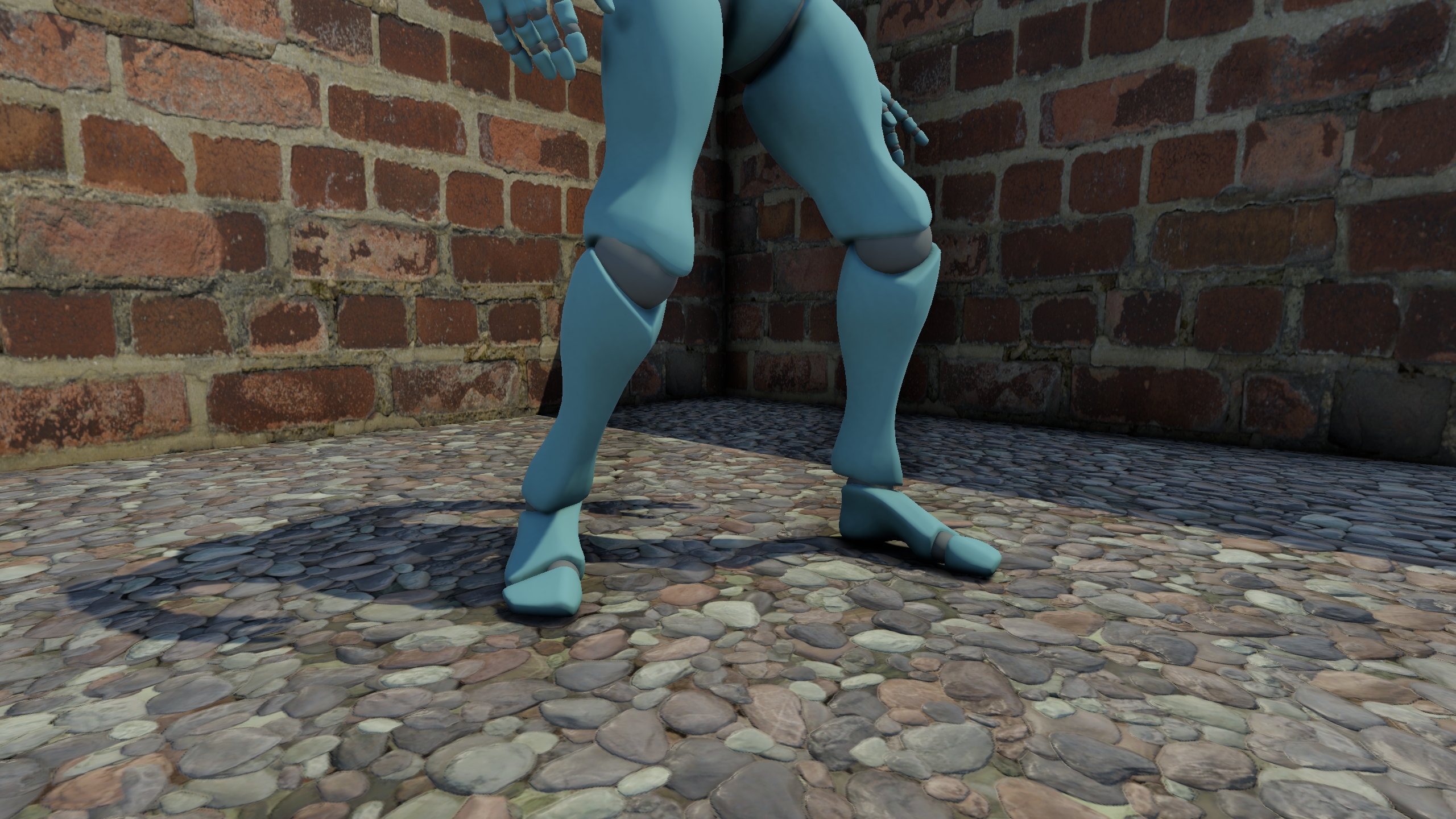
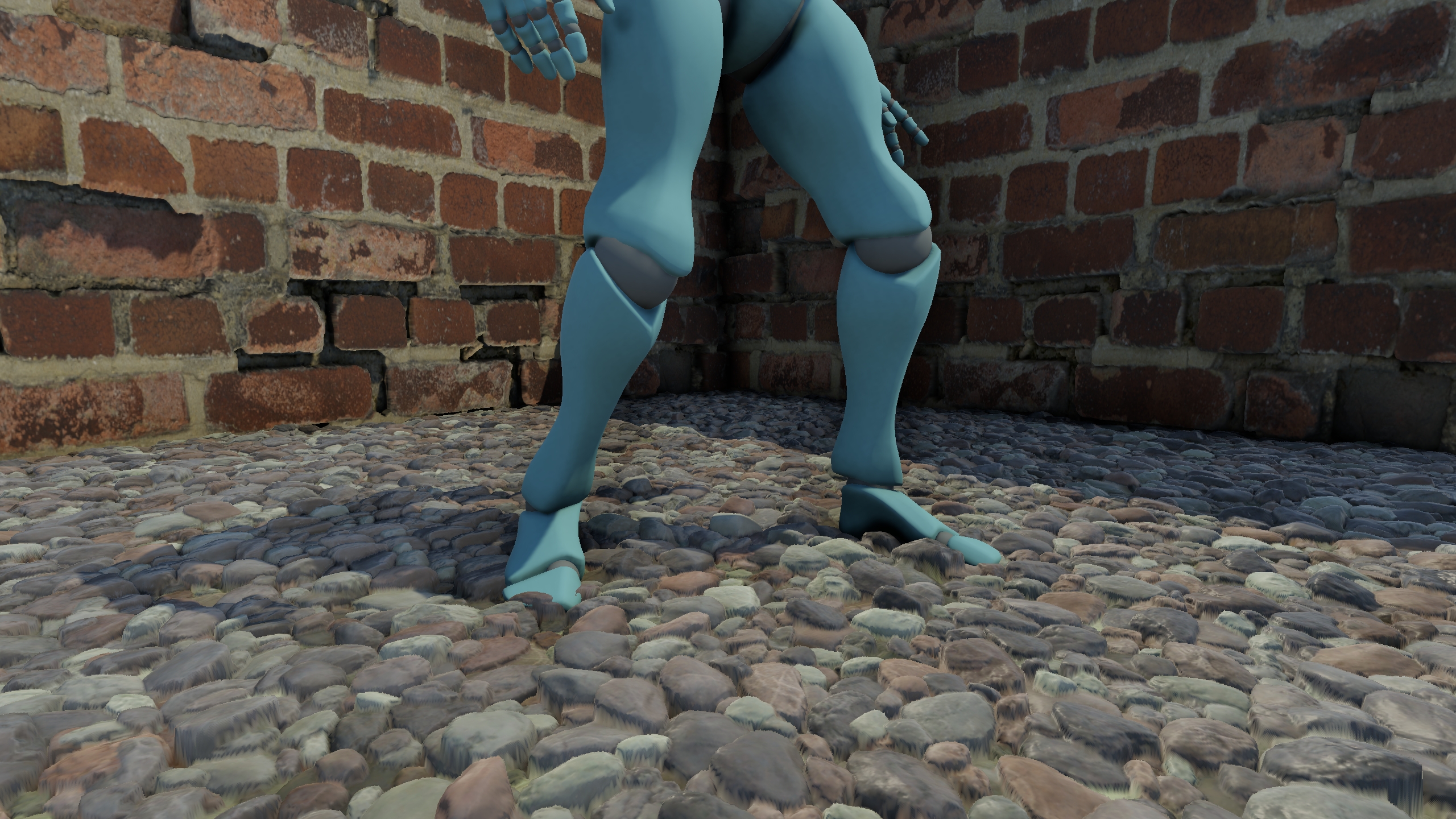
Notice that rayPosTS, which is where we will start raymarching, is not just the uv. We add a heightDirection variable in the range [-1,1] that allows us to decide whether we want the effect to simulate depth downwards of upwards. The default is -1, which means downwards and will leave rayPosTS equal to rayOriginTS. However, there are cases where we may want the effect to go upwards.
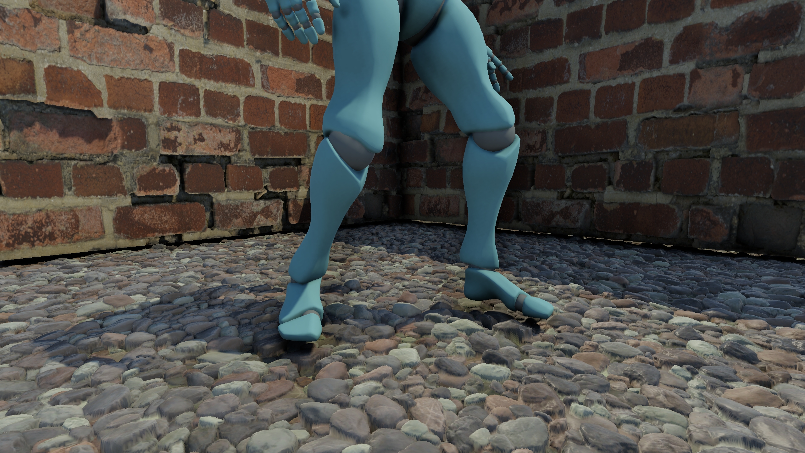
Think of a gravel material used on a floor. Using heightDirection = -1 will cause objects to hover a bit above the ground and you might be able to see the ground extend beyond walls. Meanwhile, using heightDirection = 1 will lead to proper intersection between the ground and other elements such as objects and walls:
Raymarching
Before raymarching, we must determine which mip level we will use. Otherwise, the amount of samples can't be dynamic. If we just used the highest resolution mip, we would get aliasing artifacts at a distance. Fortunately, we can calculate the mip level using screen space derivatives before raymarching using this function:
        float CalculateMipLevel(float2 uv, float2 textureSize)
        {
            float2 dx = ddx(uv * textureSize);
            float2 dy = ddy(uv * textureSize);

            float lenX = dot(dx, dx);
            float lenY = dot(dy, dy);

            float rho = max(lenX, lenY);

            float mipLevel = 0.5 * log2(rho);

            return max(mipLevel, 0.0);
        }
With that out of the way, it's finally time to raymarch the height field:
        float mip = CalculateMipLevel(uv, textureSize);
        float3 lastRayPosTS = rayPosTS;
        float lastHeight = rayPosTS.z;
        bool hit = false;

        for (int i = 0; i < samples && !hit; i++)
        {
            float height = -(1.0 - SAMPLE_TEXTURE2D_LOD(heightMap, heightSampler, rayPosTS.xy, mip).r);
            height += heightDirection * 0.5 + 0.5;
            if (height > rayPosTS.z)
            {
                #if defined(POM_LINEAR_INTERPOLATION)
                    float diffAC = abs(lastRayPosTS.z - lastHeight);
                    float diffDB = abs(rayPosTS.z - height);
                    float t = diffAC / (diffAC + diffDB);
                    rayPosTS = lerp(lastRayPosTS, rayPosTS, t);
                #else
                    rayPosTS.z = height;
                #endif

                hit = true;
            }
            else
            {
                lastRayPosTS = rayPosTS;
                lastHeight = height;
                rayPosTS += rayStepTS;
            }
        }

        if (isShadowCaster)
        {
            // Prevent precision errors by adding an offset bias in shadow caster passes
            rayPosTS += viewDirTS * POM_SHADOW_OFFSET; //I found an offset of 0.01 to be good in practice.
        }
Displaced UVs and Depth Offset
Now we know the point in texture space where the collision against the height field occurs, which is rayPosTS. The displaced uv is just rayPosTS.xy because we are already in texture space. In order to obtain the displaced world position, we must transform the displacement back to world space and add it to the current position:
        float3 rayPosOS = FromTextureSpace(rayPosTS - rayOriginTS, textureScale);
        positionWS += FromTangentSpace(rayPosOS, tbn);
        uv = rayPosTS.xy;
Given the displaced world position, we can finally write to the depth buffer using the following function:
        float GetOutputDepthFromWorldPosition(float3 positionWS)
        {
            float4 positionCS = TransformWorldToHClip(positionWS);
            float z = positionCS.z / positionCS.w;
            return z;
        }
Dealing with silhouettes
Parallax mapping assumes a planar representation for each pixel. When the effect is presented with high displacement offsets on non planar meshes, you start to see the limitations of this technique. As the ray progresses through the surface, it should actually bend following the surface curvature, but we don't have the geometric information required to do that in a fragment shader. Besides, even if we did have the mesh data required to achieve that, it would probably be too expensive.
One way to overcome this problem, is to mathematically approximate the curvature. This is what Manuel M. Oliveira tried in his 2005 paper An Efficient Representation for Surface Details .
The idea is to do a preprocessing step of the mesh to obtain two coeficients that define a quadric surface for each vertex, and store it as an attribute. During raymarching, the quadric surface height is calculated using the curvature coeficients and the ray displacement. This leads to a situation in which a ray may enter the surface, and exit it without colliding against the height map. In that case, the pixel is considered to belong to a silhouette and is therefore discarded.
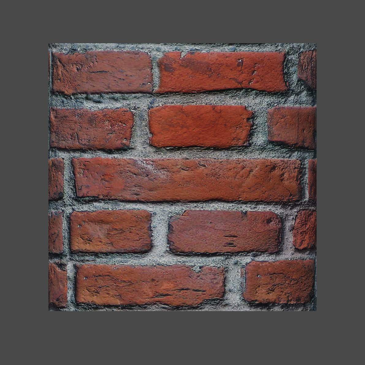
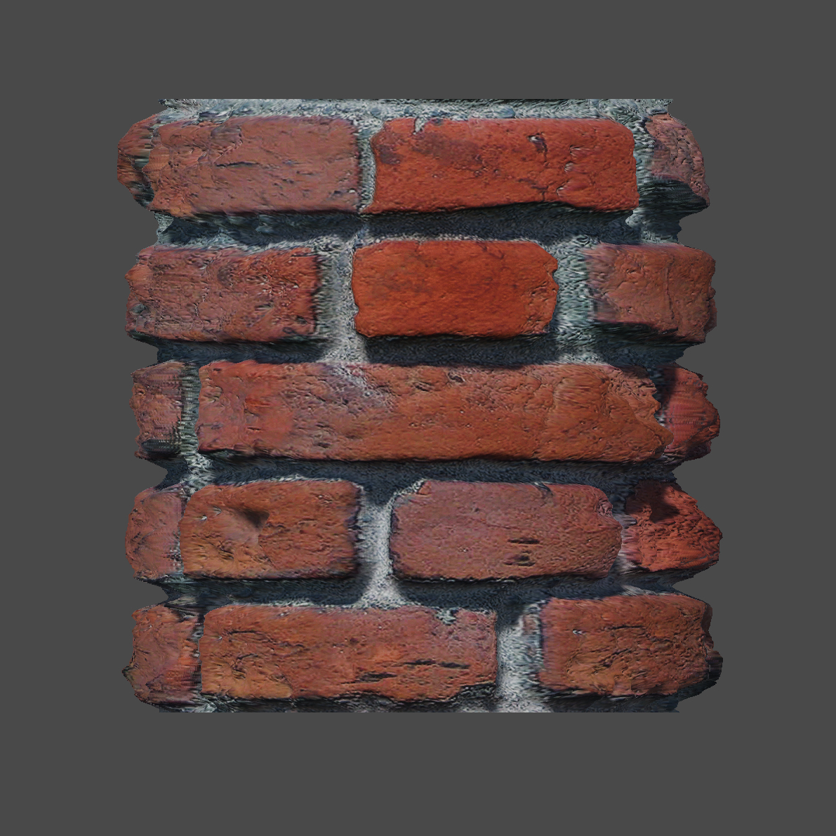
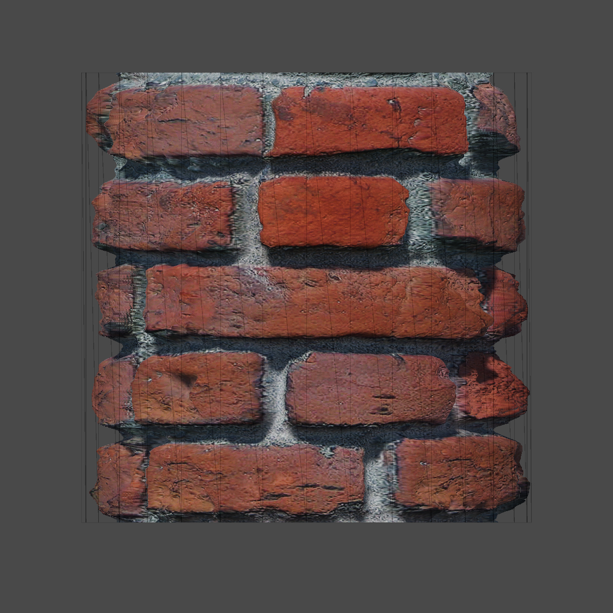
Don't get too excited though. In theory, this should improve the look of parallax effects significantly and provide accurate silhouettes. However, in practice, I found out that this approximation breaks even in simple test cases. For me, the biggest problem is that when the quadric surface does not resemble the actual geometry complexity, it will discard pixels where geometry is actually present. This artifact was a deal breaker for me, so I entirely scratched the idea of approximating the surface curvature.
Besides, the parallax effect is good enough when the displacement is small, which is always going to be the case when using parallax. For more intense displacement factors, tessellation is preferred because it provides more accurate shadows, perfect silhouettes and no aliasing.
Results
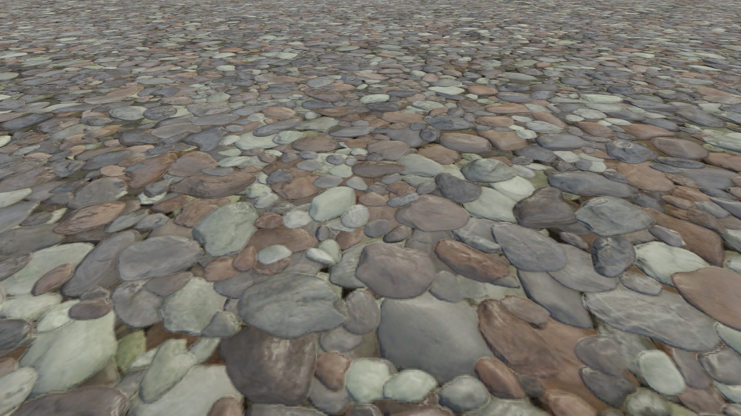
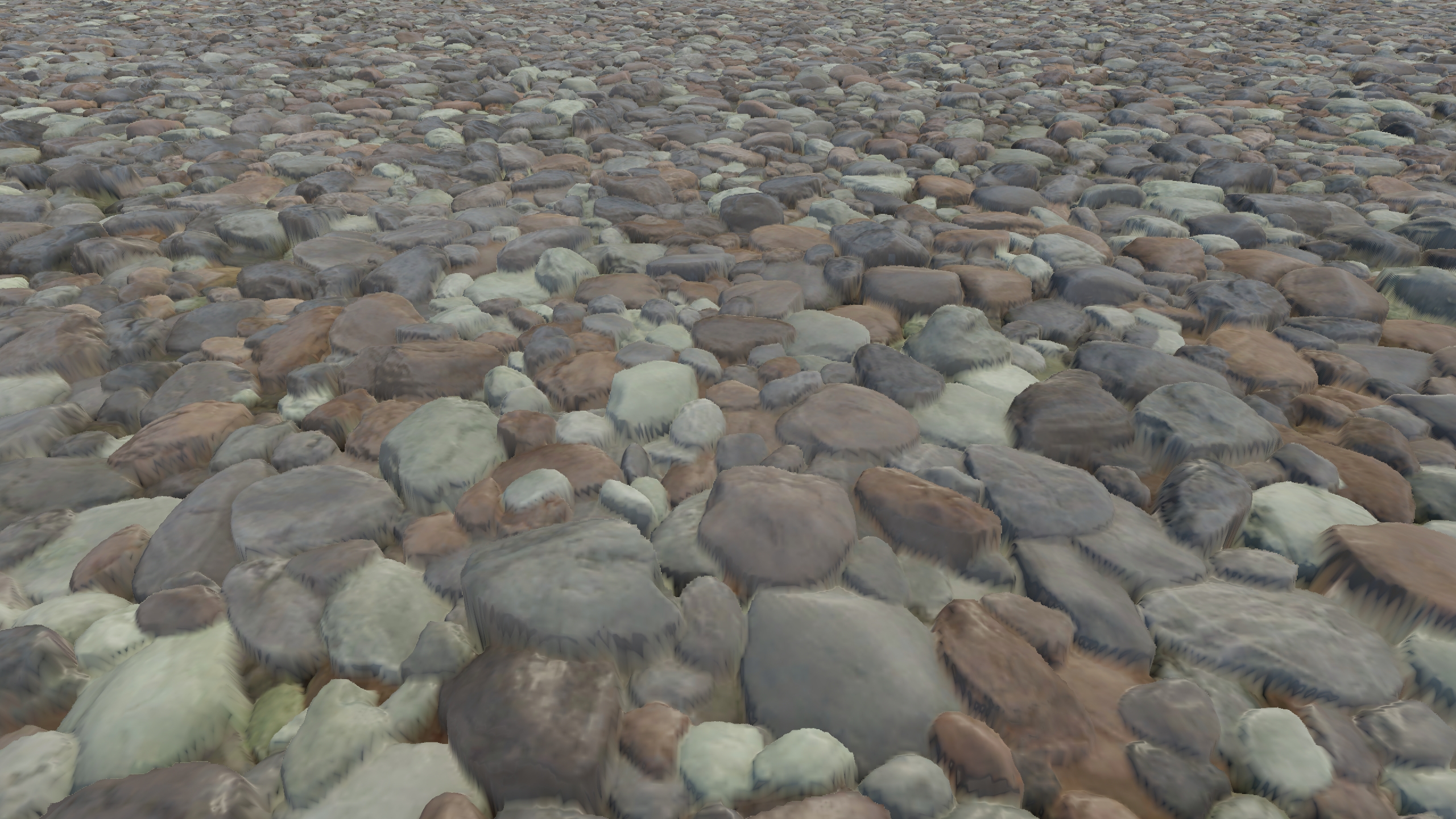
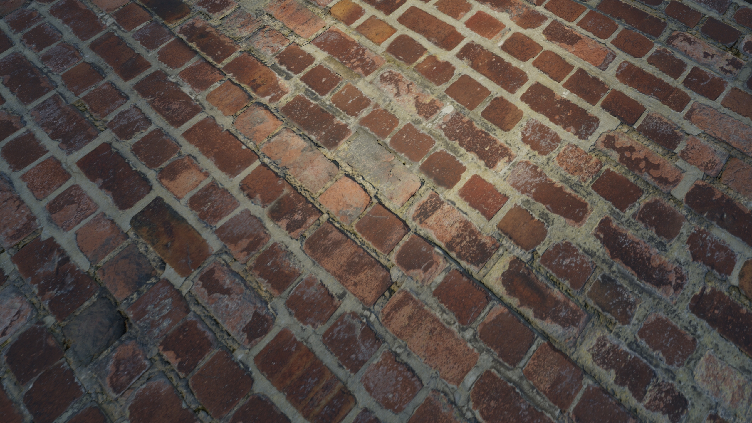
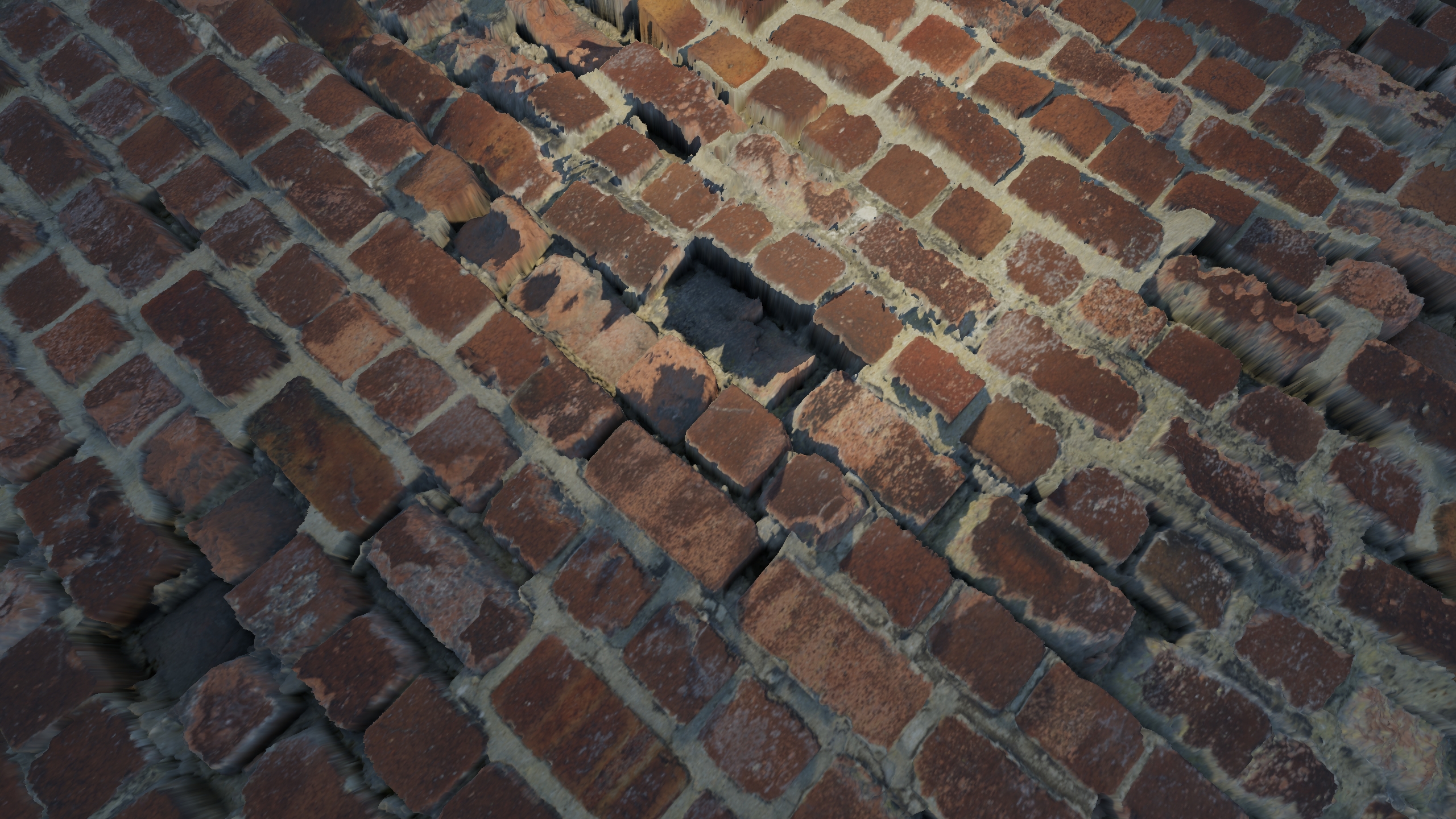
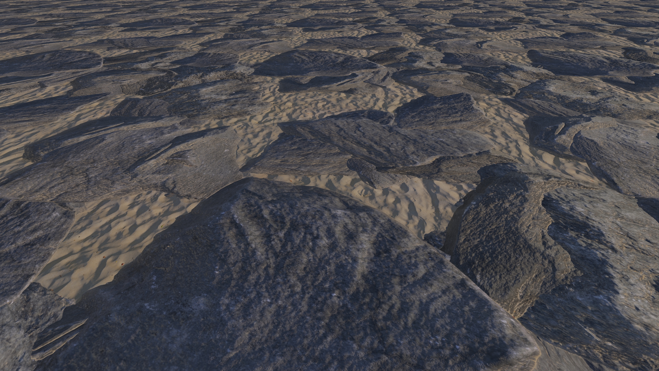
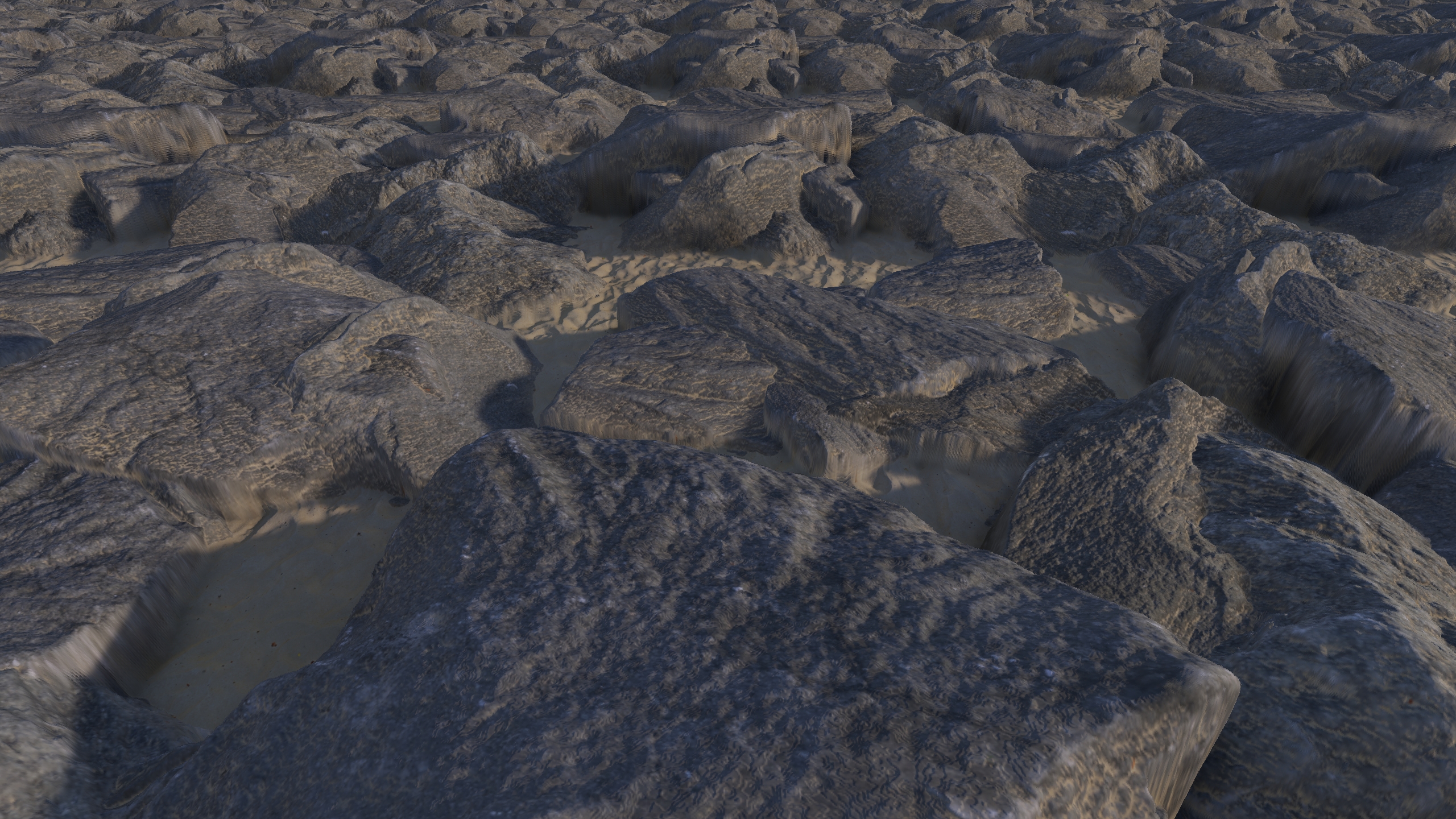
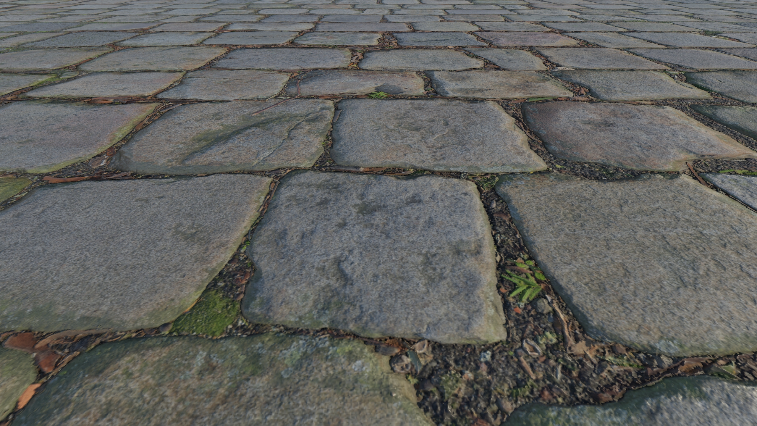
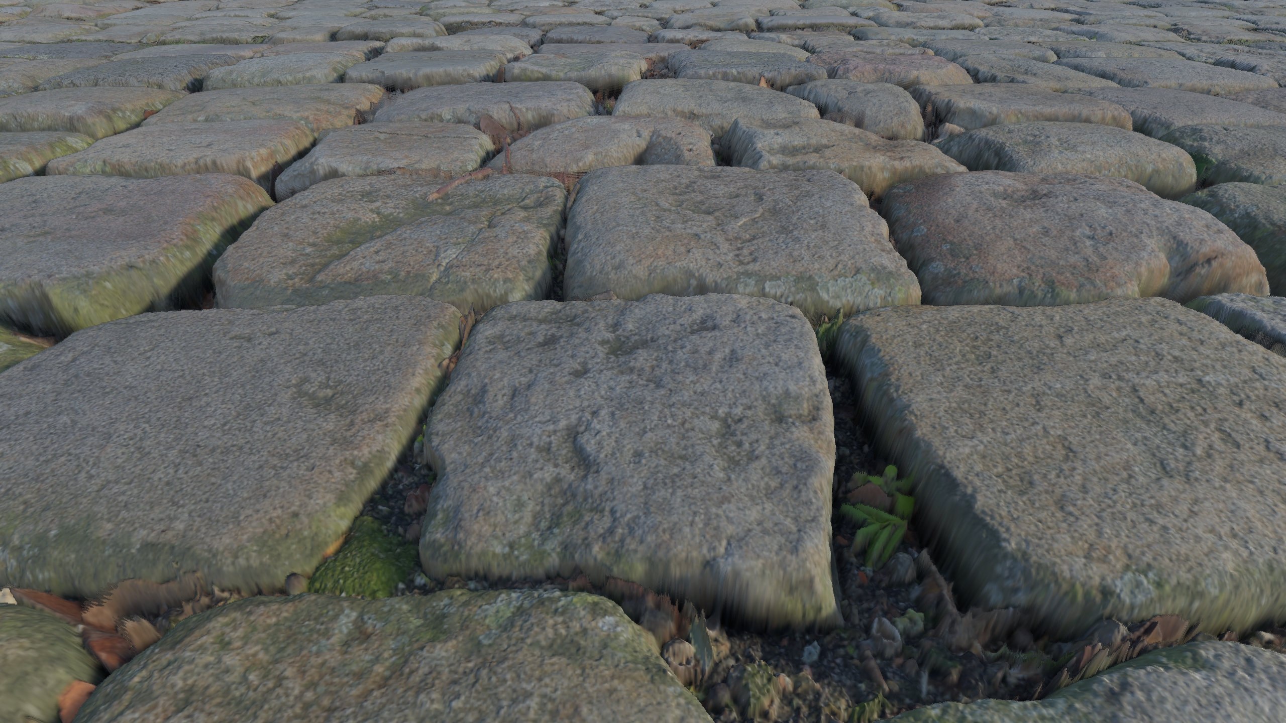
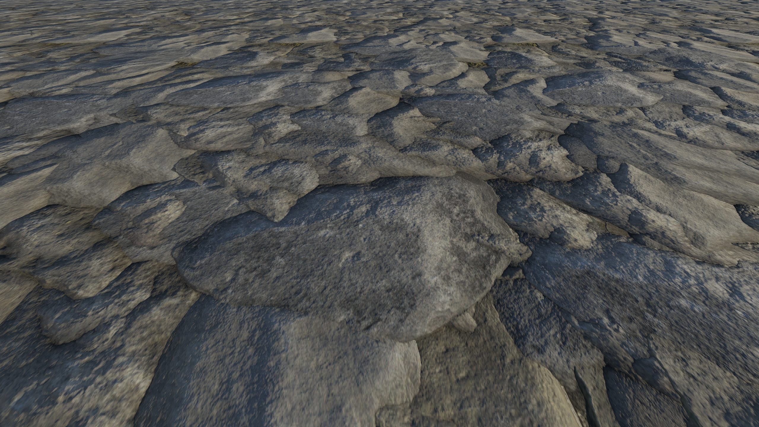
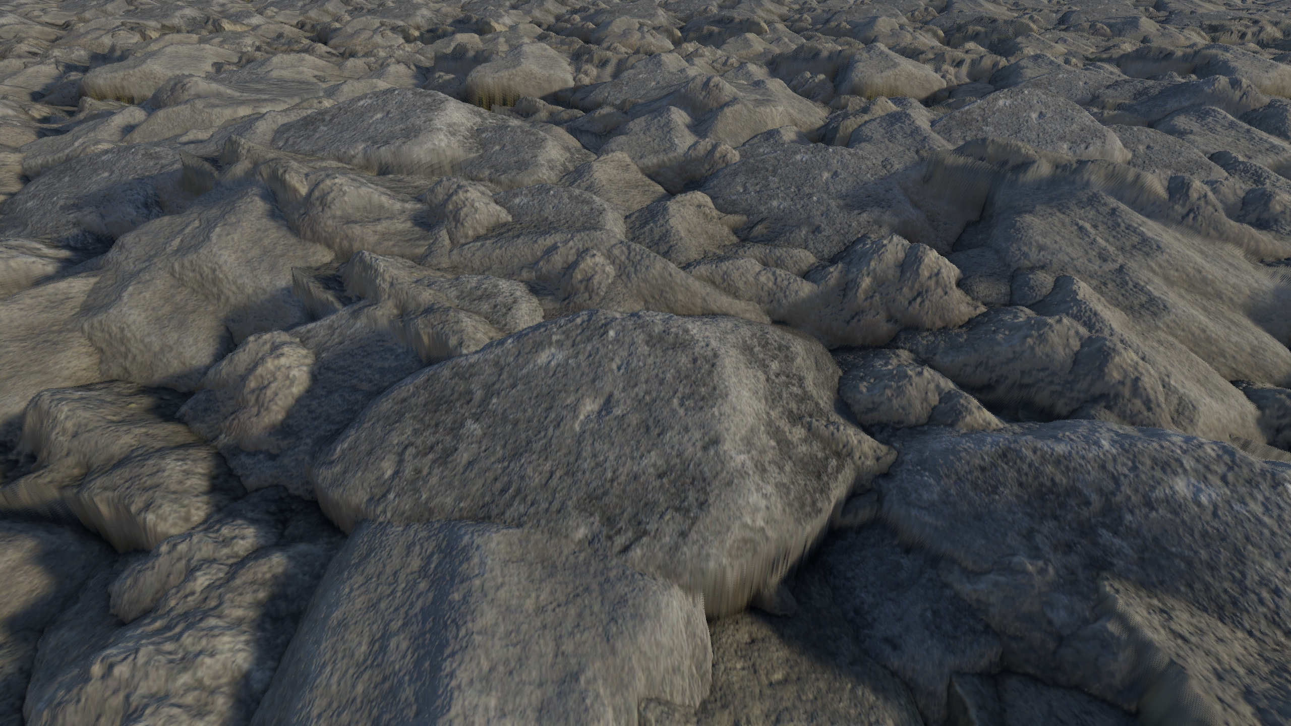
Conclusion
I think it's clear that parallax mapping works really well in certain scenarios, but fails completely in others. As I stated previously, I will be using it only on thin surfaces that are mostly planar or with a very soft curvature. For more complex surfaces that require more intense displacements, I'd use tessellation for better results. That said, parallax mapping has certain properties that can make it a better choice over tessellation:
- Highly irregular height maps: Parallax Mapping offsers per-pixel displacement, whereas you would need to tessellate the mesh aggresively to obtain similar fidelity.
- Performance: Tessellation can be quite heavy on low-end hardware, whereas parallax can look really good with a small amount of samples on thin surfaces. Besides, since parallax works per pixel, the further you are from an object the less expensive it gets to compute the parallax effect for it. That means that the computational cost of parallax mapping scales automatically with view distance.
Going Forward
In my opinion, this parallax mapping implementation covers really well the necessities of my team, but there is at least one aspect of it that I'd like to improve on: Self Occlusion Shadows.
Currently, self occlusion works by writing to the depth buffer not only in the G-Buffer pass, but also in the ShadowCaster pass. That way, what the light "sees" is a displaced version of the surface, similarly to what would happen if tessellation had been used. The problem is that shadow maps can't capture all the surface details due to resolution constraints.
In forward rendering, it would be possible to do additional raymarching steps in the height field to determine self occlusion against each light. However, we are using deferred rendering, so the height map is not available by the time lighting calculations occur. Besides, I can imagine raymarching multiple times is not a light-weight solution to the problem.
My proposal is using Screen Space Shadows. This technique calculates shadows by treating the depth buffer as a height field, and raymarching towards lights. It is not a replacement for shadow maps, it is meant to complete shadow maps. For that purpose, raymarching is executed for a very small distance, ideally to capture the details that the shadow map could not handle. The great benefit of using Screen Space Shadows is that it will not just benefit parallax mapped surfaces, it will improve shadow quality for everything. The performance penalty may be similar to the previously mentioned method, but there is an important difference: In Deferred rendering, lighting calculations for a pixel happen just once, independently of how many overlapping surfaces there are.
I still haven't implemented Screen Space Shadows in my custom SRP, so I'll probably make an update to this post in the future.